Support


Customer Support
Over the years, Shadin has become known for an unwavering level of support for our customers. Our staff is knowledgeable about our products, as well as the industry, and is happy to help answer any questions that you may have.
Technical Publications
Use this Technical Publication section to find drawings, installation manuals and operating manuals.
Can’t Find the Manual you are looking for?
P/N 91052XP Digiflo Operating/Installation Manual
P/N 91053XP Digiflo-L Operating/Installation Manual
P/N 91053XP Digiflo-L Service Information Letter
P/N 91202X-D Miniflo Operating/Installation Manual
P/N 91204XT-D Miniflo-L Operating/Installation Manual
P/N 91204XT-38-D Microflo-L Operating/Installation Manual
P/N 833811-01 AIS-380 RemoteFlo Fuel Flow Adapter Installation Manual
P/N 833811-30 AIS-380 RemoteFlo DC Analog Fuel Flow Adapter Installation Manual
P/N 660534HX Hall Effect Fuel Flow Transducer Installation Manual
833811-01 Fuel Flow Configuration Tool
833811-30 Fuel Flow Configuration Tool
Fuel Flow Meter Pin-Out Cross Reference
Fuel Flow Troubleshooting Tips
Fuel Flow Transducers Spec Sheet
P/N 962820-X ADC-200 Installation Manual
P/N 962830-XY ADC-2000 Installation Manual
P/N 962830A-XY ADC-2000 Installation Manual
P/N 962830A-X-S-4 ADC-2000 Installation Manual
P/N 962830A-X-S-5 ADC-2000 Installation Manual
P/N 962831A-X-S-8 ADC-2000 Installation Manual
P/N 912802 Digidata Installation Manual
P/N 912802 Digidata Operating Manual
P/N 681201-1 OAT Probe Installation Manual
Air Data Computer Troubleshooting Tips
ADSetup configuration software
P/N 8900 AMS-2000 Altitude Management System Installation Manual
P/N 8900 AMS-2000 Altitude Management System Operating Manual
P/N 8800-T Altitude Encoder Operations and Installation Manual
P/N 8800-M Altitude Encoder Operations and Installation Manual
P/N 8800-02 Landing Gear Warning System and Altitude Encoder Installation Manual
P/N 8800-02-01 ARINC 429 to Gray Code Installation Drawing
P/N 943200-10 ETM USB Recorder Installation Manual
P/N 943200-11 ETM USB Recorder Installation Manual
ETM Pilot’s Operating Manual
ETM Survey for Twin Engine Aircraft
ETM Survey for Single Engine Aircraft
ETM Survey for Helicopter
Fleetview 7.30 Software
FV Import Tool
P/N 631201 Sine to Square Converter Installation Drawing
P/N 630502 DC Fuel Flow to Frequency Converter Installation Manual
P/N 930502-04 Synchro to Frequency Fuel Flow Converter Installation Manual
P/N 930510 RS232/RS422 Converter Installation Manual
P/N 930514-00 Impeller Drum Fuel Flow to ARINC 429 Converter Installation Manual
P/N 930610-00 Discrete Buffer/Driver Installation Manual
P/N 933612-02 ARINC 429 to Serial RS-232 Converter Installation Manual
P/N 933620-00 ARINC 429 to Serial RS-232 Converter Installation Manual
P/N 933705-01 RS-232 to ARINC 429 Converter Installation Manual
P/N 933752-00 ADF DC Sin/Cos to ARINC 429 Converter Installation Manual
P/N 933753-00 Synchro Heading to ARINC 429 Converter Installation Manual
P/N 933753-01 ADF Synchro Bearing to ARINC 429 Converter Installation Manual
P/N 933800-12 ARINC 429 LS to ARINC 429 HS Converter Installation Manual
P/N 933800-24 Synchro Heading/Pitch/Roll to ARINC 429 Converter Installation Manual
P/N 934000-14A Serial to ARINC 561/568, 2 Synchro Converter Installation Manual
P/N 833520-00 ARINC-Manchester Converter (AMC)
P/N 833520-01 ARINC-Manchester Converter (AMC)
P/N 833610-01 Dual channel AIS 360 ARINC 429 LS to ARINC 429 HS Adapter Installation Manual
P/N 833610-02 Dual channel AIS 360 ARINC 429 Buffer/Isolator Installation Manual
P/N 833620-00 AIS 360 Aircraft Interface Module (AIM) Installation Manual
P/N 834510-01 AIS-450 ARINC 429 Heading, Pitch, and Roll to 3 Channel ARINC 407 Synchro Installation Manual
P/N 834510-03 AIS-450 ARINC 429 Heading, Pitch, and Roll to 3 Channel ARINC 407 Synchro Installation Manual
P/N 834511-00 AIS-450 ARINC 429 Heading to Single Channel ARINC 407 Synchro Installation Manual
P/N 833832-00 DIGITAL TO ANALOG RADAR ALTIMETER CONVERTER Label 164 to ARINC 552A
P/N 91052X Digiflo Operating Manual
P/N 91053X Digiflo-L Operating Manual
P/N 91202X-38-D Microflo Operating Manual
P/N 910501 Digiflo Operating Manual
P/N 910514/91052X Digiflo Operating Manual
P/N 911218 Digiflo Operating Manual
P/N 912001 Miniflo Operating Manual
FAQs
Have Questions?
Use this FAQ section to help find answers.
Still Have Questions?
My aircraft is 28 VDC and the transducer is 12 VDC. Is this OK?
Yes. The flow meter steps down the voltage and provides it to the transducer.
How do I change the K-factor on my flow meter?
Refer to Manual Entry Mode section of the Operating Manual. The unit must be pulled from the panel to access the switch that is used to put the flow meter into Group I configuration mode.
Do I need shielded wiring?
Yes. Shielded wiring is required. Ground the shielding on the indicator side only.
Why does the fuel flow read intermittently high?
There may be EMI noise affecting the fuel flow signal (e.g., magnetos or generator/alternator). If a Shadin Avionics (vs. Floscan) transducer is installed, a magnetic shield may be installed directly over the transducer. Contact Shadin Avionics Sales for details.
Why are the fuel flow readings erratic on a carbureted engine?
Verify that the configuration is set for carbureted not injected. Refer to the Operating Manual for details.
Can the brightness level on my Fuel Flow Management Indicator be adjusted?
Yes. The Microflo is adjustable with the toggle switch marked “Bright” on the front of the indicator. The Miniflo brightness is adjusted by turning the potentiometer located at the side/rear of the unit counter clockwise to increase the minimum intensity. The Digiflo adjustment is located on the back of the indicator through a small access hole. Using a small flat blade screwdriver, adjust potentiometer for the desired display brightness.
Can a standard Fuel Management System (i.e., Digiflo, Miniflo, or Microflo) be converted into one that can be interfaced with my GPS to show fuel required to destination, fuel reserve upon reaching destination, and nautical miles per unit of fuel? If so, how much will it cost?
Yes, depending on the serial number of your indicator. Contact Technical Support Department to confirm applicability.
Why are the fuel flow readings 50% of what they should be?
Verify that the K-factor is set properly and that the transducer is not installed backwards. Fuel must flow into the transducer through the side of the transducer marked “input”.
Why are the fuel flow readings inaccurate?
Verify that the K-factor is set properly and that there is not a 90° fitting within 3″ of the inlet.
Why are the fuel flow readings high?
The next time the aircraft is flown in cruise, turn on the boost pump. If the fuel flow drops, this indicates that there is air leaking into the fuel line upstream from the transducer. It is possible that air is leaking into the system through the selector valve or other connection. Consult with your avionics shop and have them contact Shadin Avionics Technical Support Department to troubleshoot.
How do I verify the software version of my fuel flow indicator?
Press the ENTER/TEST button for approximately three (3) seconds to initiate the self-test mode. The last screen displayed before returning to the fuel flow screen displays the software version.
How do I verify the K-factor currently programmed in my unit?
Press the ENTER/TEST button for approximately three (3) seconds to initiate the self-test mode. The first item displayed after “GOOD” is the K-factor expressed in thousandths (e.g., 29.6 = 29,600 pulses).
On engine start there up and down fluctuations in the fuel flow for the left engine on my Shadin indicator. Does this sound like an intermittent connection on the transducer?
Generally, if a fuel flow indication is higher than the actual flow of the engine it is due to electrical noise. Shadin recommends shielded wiring going out to the transducer with the shield grounded at the indicator and left floating at the transducer end. Regardless of what other manufacturers say, all units are susceptible to noise if the field is strong enough. Using proper grounding, and shielded wiring, is the best way to combat this issue. Moving the fuel flow wires away from high voltage sources like the magnetos and ignition harness are also good ways to reduce the impact of the electrical noise (even a half inch or so can make a difference).
Low or no flow is often a condition of a failing transducer. Reference the troubleshooting guide and verify voltages at each of the wires coming from the indicator or do the tap test to troubleshoot the system prior to ordering a new transducer.
What do I need to configure an adc2000 without using the loopback harness?
The ADC 2000 programming may be completed using a loopback harness through the use of a computer and serial / USB port using ADSETUP software. The current version and user guide for ADSETUP can be found under the Air Data tab on our technical publication’s web page. You must have software 93.00.8X (x is a variable) to use the Windows version.
Is there a procedure for us to recalibrate the altitude functions of the ADC2000?
Shadin Avionics does not have a published procedure to calibrate altitude or airspeed. All calibrations should be performed at our Repair Station. See our contact page for RMA request to return an ADC 2000 for calibration.
ADC-2000 (P/N 962830-3) in a Beechcraft King Air: We do not want to use the fuel portion of the FADC is that okay?
Yes, the interfacing device will typically look and see that fuel flow is not available on the serial string and ignore it for alternate source.
Setting up a ADC2000 air data computer: the computer I have only has USB ports will this work?Do I need a computer with a serial port to complete this so my computer can talk to this?
Most new computers do not come with a COM port. You can purchase a USB to serial adapter from several online retailers to make the ADSetup software communicate with your computer. You can also find our ADSetup software under the Support section of the website in Technical Publications.
I have an ADC 2000 (962830A-1-S-4) that is about 50 feet out at all altitudes. Is there any way to correct this? Or will I need a new ADC?
No need to replace the unit. Simply submit an RMA request under the Contact section of the website under Repair Station. A representative will be in contact with you to set that up. Typical turn times on repair are 2-3 weeks and if a quick turn is needed ask us if we have exchange units available. These can typically be provided quickly if on hand.
Why is the wind information not displayed or incorrect?
Make sure all the components that make up the wind calculation are correct. This includes OAT, TAS, Ground speed, Heading, and Track.
Why doesn’t my ADC communicate with my GPS?
Verify that the input and output on both the ADC and the GPS are set Correctly. Refer to the Shadin Avionics ADC-200 or ADC-2000 Installation Manual Loop Back procedure and the GPS Operating Manual for details. For your Shadin Avionics Digidata, refer to the Configuration section of the Operating Guide.
Why is the fuel flow read-out inaccurate?
Verify that the K-factor setting programmed into the unit matches the K-Factor imprinted on the side of the transducer. Refer to the Digidata Operating Manual, Configuration Section 6 for detailed procedures.
How do I verify the K-factor currently programmed in my unit?
The Digidata displays the K-factor by moving the toggle switch to TEST/ENTER position and holding it there for ten (10) seconds. For the ADC-200 and ADC-2000, refer to the Installation Manual Configuration Section 9.
How do I set the K-factor?
Refer to Section 10 of the install manual for the table indicating the proper settings for the four (4) switches on the back of the ADC-200 and ADC-2000. For Digidata, refer to the Operating Manual and Section 10 of the Installation Manual for Drawing No. 4028-716. With the special ‘loop back’ harness, it’s a simple 4-step procedure.
How do I configure my ADC?
There are two (2) methods. Refer to the “loop-back” procedure in Section 9 of the Installation Manual. The second method is the “ADSetup” program which can be accomplished through your PC.
What is the minimum level software version that communicates with the Garmin GPS?
The minimum software version required without a Shadin Avionics fuel flow meter is 93.XX.61. If a Shadin Avionics fuel flow meter is part of the installation, the minimum software level version is 93.XX.77.
Why does the winds display shows dashes after I’ve been in a turn or accelerated or decelerated?
If the aircraft has been in a turn, or has accelerated or decelerated, the winds information dashes out after holding the last valid wind information for three (3) seconds. The winds information will again be displayed continuously when the aircraft has maintained a steady course and airspeed for at least forty (40) seconds. If heading and magnetic track differ by more than 40 degrees, no wind information will be displayed.
How is the head-or tailwind calculated?
This component is derived from the difference between ground speed and air speed.
How is True Air Speed (TAS) calculated?
Indicated Air Speed (IAS) and Outside Air Temperature (OAT).
My aircraft is 28 VDC and the transducer is 12 VDC. Is this OK?
Yes. The Shadin Avionics Air Data Computer steps down the voltage and provides it to the transducer.
What does “EN N-RDY” on the display mean?
The AMS-2000 requires certain jumper settings for different inputs from your encoder. If they are not correctly configured, this error message appears. For set up procedures, refer to the Installation Manual drawing 4089-024. This message also appears when the aircraft is above or below operating altitude range.
What does “EN ERROR” message mean?
Possible causes include: the unit may be receiving an invalid input from your encoder, or the wiring may not be correct. Consult with your avionics shop and have them call Shadin Avionics Technical Support Dept. to troubleshoot the problem.
The back of the unit has an opening marked “S2” and “S3” in which three (3) sets of holes are visible. Which is “S3”?
The AMS-2000 must be configured for input signal (gray code or serial). From left to right, S2 is the first set of holes and S3 is the second (middle) set of holes. Refer to the installation manual for more details.
Why is my altitude reading inaccurate on the AMS-2000 but not on the transponder?
The encoder input is incorrect. Unless your encoder is a Shadin Avionics Falcon Encoder, P/N 8800-X, it may not have high altitude capabilities (D4). You may need to check the jumper setting to disable this option. Refer to the installation manual for more details.
Are the gray code lines of the AMS-2000 internally isolated?
No. Diodes may need to be installed in the harness.
My AMS-2000 reads in 100 foot increments. Is it possible for it to read in 10 foot increments?
Yes, with serial input from a Shadin Avionics Altitude Encoder, P/N 8800-X.
ETM consistently overestimates the fuel consumption but the K factor is set correctly (we had it checked by the service center). Is it allowable to modify the K factor to account for that? What is the recommended procedure?
Go to the support section under Technical Publications and download the Fuel Flow Troubleshooting Tips. In that document is a troubleshooting procedure for inaccurate fuel flow readings. If your indicator K-Factor is not programmed to match the transducer K-Factor your fuel flow will under or over read fuel flow by the same percentage your K-Factor is off. Typically reading the K-Factor that is stamped on the transducer or fire shield box assembly and programming that into the indicator will fix the problem. Using the troubleshooting sheet is a last resort if the K-Factor of the transducer is unknown.
I have a Shadin engine trend monitor in a TBM 700C with the old-style key reader. What does it mean to Wrap the key??
The “Key Wrapped” message means that the key was not downloaded soon enough, and the processor has started to write over previously recorded data and will not longer be useable. Shadin released a new USB recorder with much more memory (enough to last for the life of the aircraft) and should be something to consider for a future upgrade to the system as a plug and play installation.
Is it possible to increase the amount of data saved to the recorder?
The “DataKey” has a limited amount of data. There is an upgrade option which is a plug and play replacement to switch over to a USB type recorder with the thousands of hours’ worth of storage.
I get a pop-up message on every flight: “Key 91% full.” How do I resolve this?
Read the Key, this requires special equipment “key readers” that are no longer available from Shadin Avionics. It is recommended that you switch over to the USB Recorder.
Why do I need the Shadin Avionics ETM?
Engine trend monitoring detects engine problems before secondary damage occurs. It may extend the aircraft’s TBO which could result in dramatic savings. The Shadin Avionics ETM can reduce engine maintenance costs, reduce down-time, and increase the market value of the aircraft.
Why is “WRONG KEY” being displayed?
Each key is data-stamped with the parameters of an individual aircraft. It is possible that a key specific to one aircraft being inserted in the wrong aircraft. Another possible reason is that parameters in the ETM may have been manually changed. Re-initialize the key after reading it using your PC and Key Reader.
What does “Memory Status Bad 12345ABC” mean?
The ETM has lost the configuration settings in the internal memory. The ETM processor will need to be returned to our FAA Repair Station for service.
What is the default password set at the factory?
Shadin Avionics sets the password at “A”. This password remains until it is manually changed to a customized password of your choice. It is recommended that you record the password in a safe place.
What if I forget my password?
It is imperative to remember your password, or the unit must be returned to the factory for repair.
Will the Shadin Avionics ETM record exceedance data even if the key is not installed?
Yes. The Shadin Avionics ETM will continue to record exceedances in the exceedance file review section.
What do I do if the fuel flow read-out is incorrect?
Ensure the K-factor is set correctly to match the K-Factor imprinted on the side of the Transducer. Refer to the Engine Entry File chapter of the Security Section “Selecting the Fuel Flow K-Factor” procedure in the Configuration Manual.
How often should the Data Key be downloaded?
It depends on how often the aircraft is flown. Shadin Avionics recommends downloading the Data Key as often as possible, or at least once per week.
How will I know when my data key is full?
The display will start flashing when the key is 80% full, and report the memory used in 5% increments thereafter.
What will trend monitoring identify?
Hot section deterioration, hot starts, faulty fuel nozzles, dirty compressors, foreign object damage, bleed leaks, and instrumentation errors.
Why should I monitor my engine trends?
Early detection of engine problems may prevent costly secondary damage. It will lower engine maintenance cost, increase safety, reduce down-time, and increase the marketability of your aircraft.
When should a trend monitoring program be implemented?
Engine monitoring may begin at any time; the most accurate baseline is obtained when trend monitoring is implemented within the first one hundred (100) hours of engine life or once newly overhauled. If trend monitoring is started two to three (2 -3) months prior to overhaul or hot section inspection, it will provide a means of judging the effectiveness of a hot section or overhaul.
How much does the system cost?
Compare our system quote to the cost of a hot section inspection saved by using a Shadin Avionics ETM, and consider the cost of preventable, major repairs from deterioration in the gas path.
Why is the Shadin Avionics ETM automatic trending better than the hand-trending?
Automated, non-biased record keeping eliminates the (subjective) human factor and saves hours of manual work.
Will the Shadin Avionics ETM show me how the engine is doing by the fuel flow or by the temperature of the turbine section?
Yes. It also displays torque, NG (gas generator speed) and NP (prop speed).
How long does the average ETM installation take?
This depends entirely on the number of engines, the installer’s experience and whether the aircraft is already open for other modifications or not. An average ETM installation is 24 – 60 hours. Contact your local avionics shop for a firm quote.
What is the cost/time required to trend data from the Shadin Avionics ETM automatically?
Trend houses like the Trend Group and DETA-TREND turn data analysis around in graphical format in less than six (6) hours.
Can the Shadin Avionics ETM replace a different manufacturer’s system installed at the factory?
Yes. Contact your Avionics Shop for details.
Does the Shadin Avionics ETM do the trending? How does it relate to the P&W ECTM program?
No, It records the data to be trended. The Shadin Avionics Fleetview program assists this process and is now available in an easy-to-use WindowsTM format. The Shadin Avionics system is compatible with the P&W ECTM program.
Does the Shadin Avionics ETM record exceedances? Cycles? Starts? Hot starts?
Yes. With the new Shadin Avionics Fleetview program in Windows format, this information is even easier to view.
How is “exceedance” defined?
Exceedance is an event when the engine is pushed to parameters beyond the aircraft specifications. Shadin Avionics’ ETM system is based on the airframe manufacturer’s specifications which may differ from Pratt & Whitney’s engine model specifications
Aside from engine trending, what are the other features offered by the Shadin Avionics ETM?
The Shadin Avionics ETM system provides fuel flow, air data, and back-up navigation information. It also serves as a digital backup to the engine gauges.
What happens if you wrap the DataKey?
Contact Shadin Avionics Technical Support Dept. for procedural details.
What if my aircraft isn’t listed on your STC list?
We may be able to help you with a Form 337 Field Approval or mutually pursue an STC. Contact Shadin Avionics Sales.
What is the Pratt & Whitney H/ECTM?
This is trending software provided by Pratt & Whitney that Shadin Avionics’ Fleetview program interfaces with that graphs ITT, FF, etc. over the course of the life of the engine.
What kind of parameters are custom configured on the ETM for my aircraft?
Your aircraft serial number, GPS models, reminder for annual inspections, fuel units of measurement, engine serial number(s).
What are the benefits of having my Shadin Avionics ETM interfaced with my GPS?
When the Shadin Avionics ETM is interfaced with your GPS, fuel management information, air data, wind direction and speed, etc. are displayed for your reference.
In Fleetview what does “Cannot set key reader baud rate”, “Key reader port is invalid” or “Could not initialize port” mean?
There is a problem with the COM port setting. Make sure you are using the current version of Fleetview.
I am installing a AIS-380 (DC Fuel Flow Adaptor) to interface RS232 Fuel Flow out to a GTN750Xi. The Garmin says use Fuel Format 1; what setting do I program into the AIS380 (Shadin_Z or _G)?
The Fuel flow adapter should be configured to either Shadin_G or Shadin_Z serial output format. The Garmin GTN should be programmed to FADC Format 1.
Will the AIS-450 provide an output signal for the FDR on the heading, roll, and pitch of sufficient quality to qualify to the FDR requirements?
The AIS-450 will output a standard voltage per ARINC 407 synchro format for heading, pitch, and roll.
Can one of the Shadin Avionics 933612-0X be used to provide RS-232 data two (2) EFBs?
Yes, if the RS-232 is valid you the output can drive two (2) EFBs.
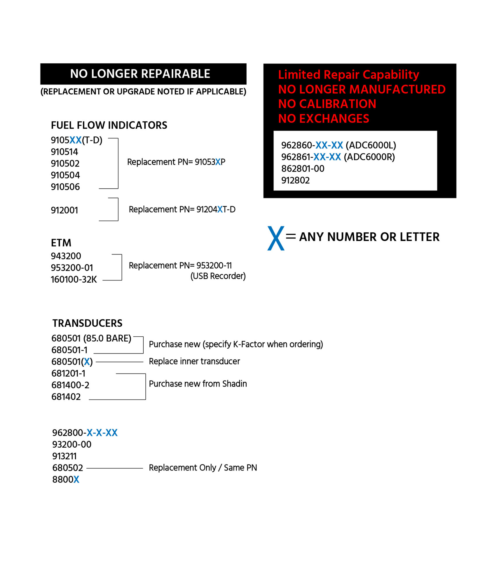
Repair Station
Shadin Avionics operates a certified FAA and EASA Part 145 Repair Station. Having troubles with a Shadin part? Our team is available to support and repair your Shadin products. Check here to see if your part is unrepairable or obsolete.
Please note: If you require an EASA, enter the following statement onto your PO “Repair P/N XXXXX IAW approved Shadin design documentation”. Be sure to enter the part number being repaired in place of the X’s. We are unable to issue the EASA without the statement on the document. If you do not require an EASA, please remove the request or inform us of the change.
(Please send repairs to 7555 Market Place Drive, Eden Prairie, MN 55344)
*A shipping account number is required for all international shipments*
“The depth of knowledge in your product by your team is extensive and immediately obvious. When technical questions are raised, Shadin provides immediate and comprehensive answers.”


LET'S
CONNECT
7555 Market Place Drive
Eden Prairie, MN 55344
952-927-6500
LET'S
CONNECT
7555 Market Place Drive
Eden Prairie, MN 55344
952-927-6500